My 2nd year presenting a topic in PQSynergy. It has been an enjoyable 2-day conference.
Made new friends and learnt new things from fellow practitioners. Glad to have met the guys from Sonel too.
Will definitely take a closer look at some of your instruments.
And congratulations to Terry Chandler and his Power Quality Thailand on another successful conference.
Happy 30th anniversary, PQT. Many more good years ahead.
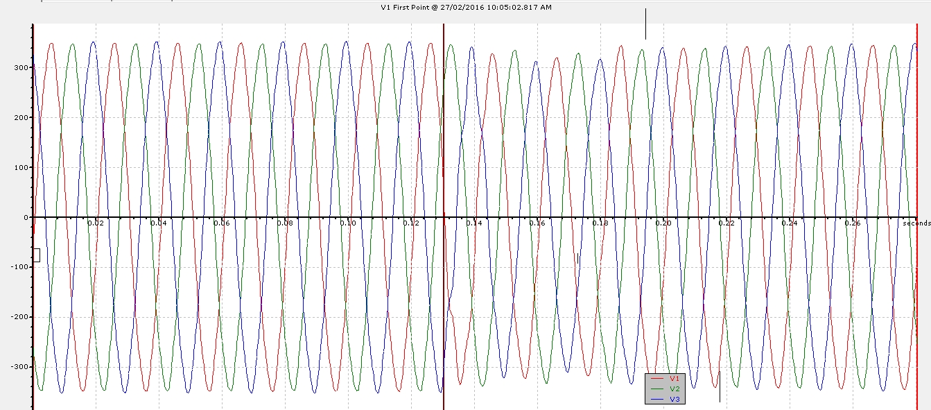
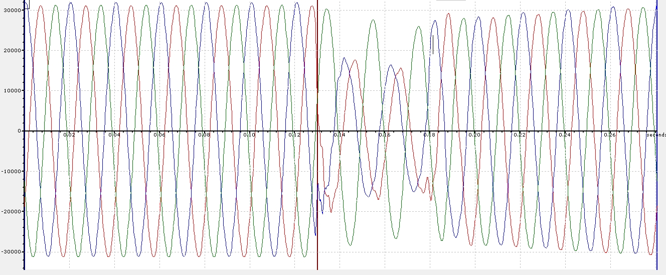
Just a while ago, the following waveforms were captured from monitors in Jurong East and in the River Valley area, indicating a transmission fault, likely to be originating from the South block of Singapore. Waveforms captured in the River Valley area indicated a single-phase fault on L1 (Red) at 230kV transmission voltage.
Captured at LV (West area)Captured at 22kV (South area)
Added the following screenshots obtained from a PQUBE, being monitored in South of Singapore, at Low Voltage. Thanks James!
Earlier this afternoon in the midst of the year-end festive mood, you might have seen your office lights flickered twice in an hour: two transmission-level faults occurred. Tell-tale signs were from the nature of the waveforms and that in general, everyone in Singapore ‘felt’ it, with 1/4 of the island getting the ‘worst-magnitudes’.
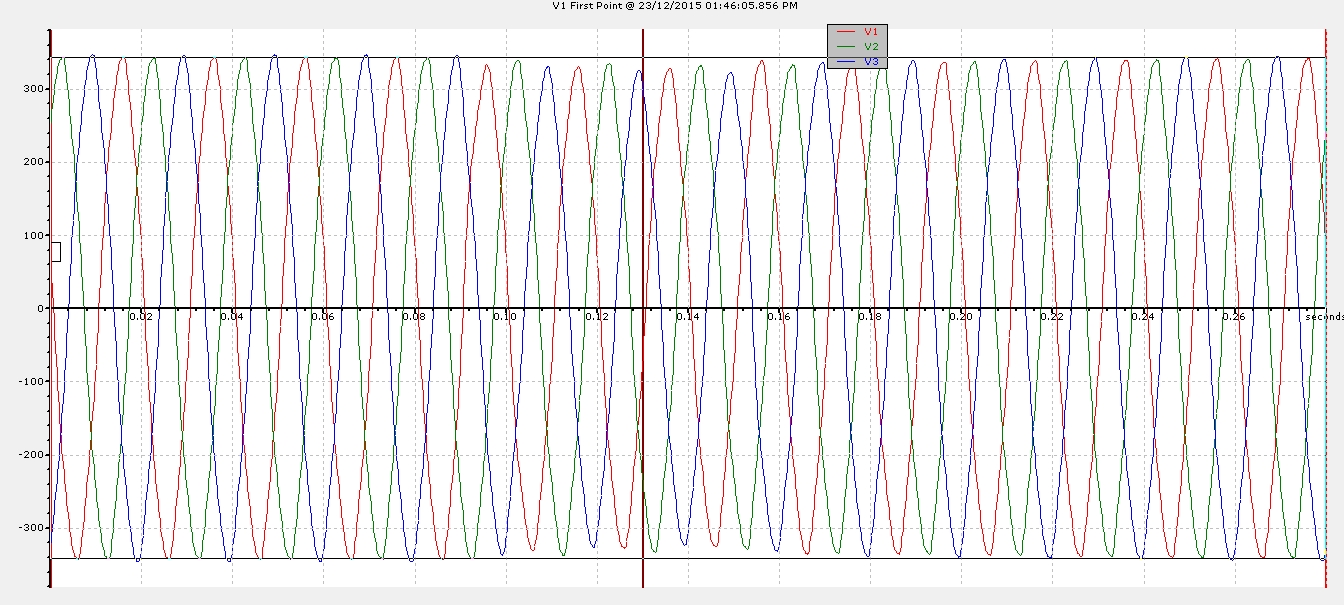
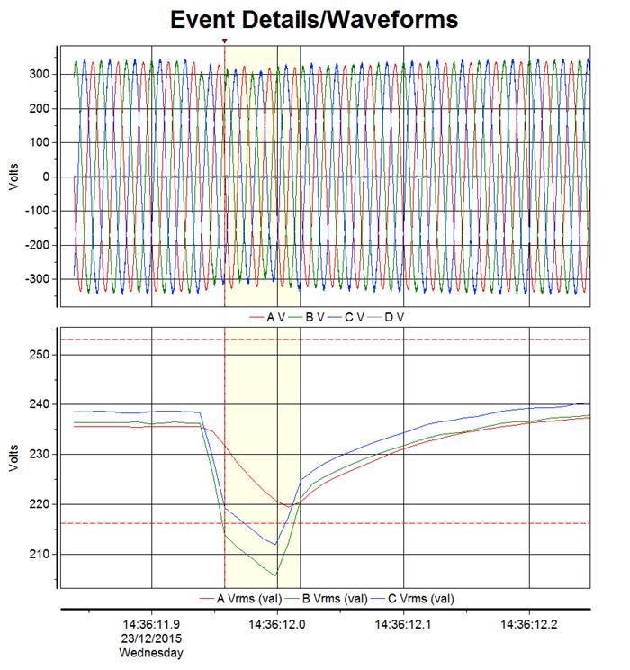
One at around 1:46pm and the other at 2:36 PM. The following were captured from an office in Jurong East and in Bedok area (at low voltage).
At 1:46PM, it can be seen that the dips were fairly shallow. Hence it can be deduced that the origin of the fault were neither in the 230kV blocks that these two sites are located. From the RMS trend of the waveforms captured at Site 2, it can be inferred that it was likely a single-phase 230kV fault on Phase L1 (Red).
Fig1: Site1 Jurong East 1346hrsFig2: Site2 Bedok 1346hrs
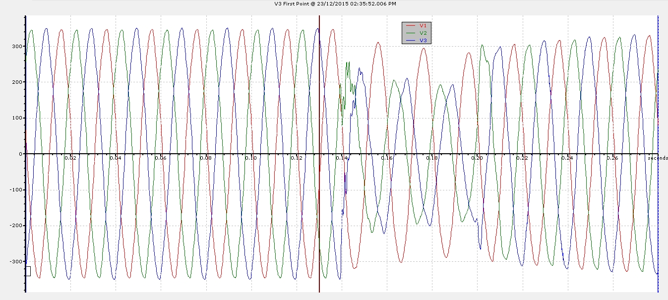
At 2:36PM, the dips were much more pronounced at Site 1, suggesting that it resides in the same 230kV block as the fault. Here it is very clear that the 230kV fault was on the Phase L3 (Blue). At the second site at Bedok, the dips were again shallow. These are characteristics of a 230kV transmission level fault in Singapore. Only 1/4 of the island will be most affected with dip magnitudes in the range of 40 to 50% (dip by).
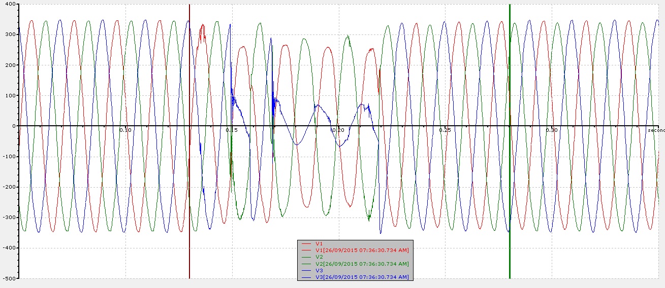
Earlier in the morning today, there was a localized voltage dip (dip by ~ 80%) in the Jurong East area. From the waveforms captured, it can be inferred that there was a 22kV L3-L1 fault.
Sensitive equipment was likely to be affected, especially those sensitive single phase LV control circuits taking in on Phase L3.
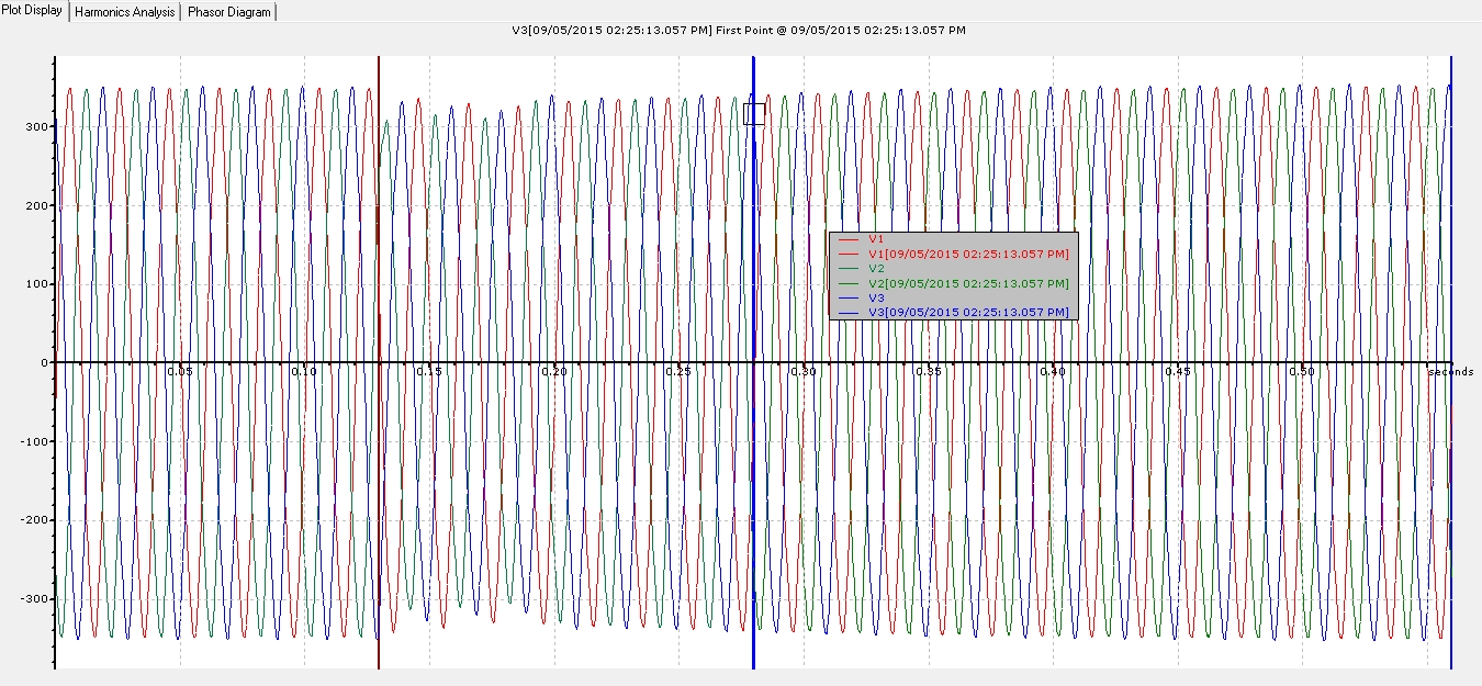
Earlier at 2:25PM, there were voltage dips reported all over the island.
This is the waveform captured at low voltage in Jurong East, typical of a 230kV transmission level fault.
This small dip in voltage here suggests that the transmission fault did not originate from this particular 230kV block, where this PQ monitoring device is located.
To many of you in Singapore, you will only probably observe lights flickering either when 1) the light bulb itself is due for replacement or 2) during the very brief moment where there was an electrical fault in your area.
You will also not find the word ‘flicker’ in Singapore’s Transmission Code. but that does not mean there are no flicker limits imposed for Singapore’s electrical network. In Section F2.1, it states that “…………shall be in accordance with the requirements set out in Engineering Recommendation P28 of UK.” Based on this old ER P28, the limits are 1.0 and 0.8 for short (PST) and long term (PLT) severity values respectively.
So what is flicker, you may ask?
Flicker is a power quality problem primarily concerning human’s perception of changes to the output of the light bulb. These changes are caused by voltage fluctuation due to electrical loads with rapid variations in its loadings. An arc furnace is often cited as an example.
PST 1.0 refers to the level of voltage fluctuation that will cause more than 50% of you to notice and complain. It is based on the changes of the light output of a 60W incandescent light bulb. One can measure these flicker values either using a Flicker meter or a modern power quality analyzer.
So are there flicker issues (exceeding limits) in Singapore? I will say, there are flicker issues here but not necessarily a problem. Remember, the limits set upon was based on the incandescent light bulb, which you hardly come across today.
An interesting study (Cigre 449) conducted by Cigre Working Group C4.108 revealed in a limited test of their own that modern lighting are less sensitive as compared to the 60W incandescent lamp, when tested under instantaneous flicker value of 1.0.
So there could very well be flicker issues in your area. It’s just that modern lighting have saved you from being irritated.
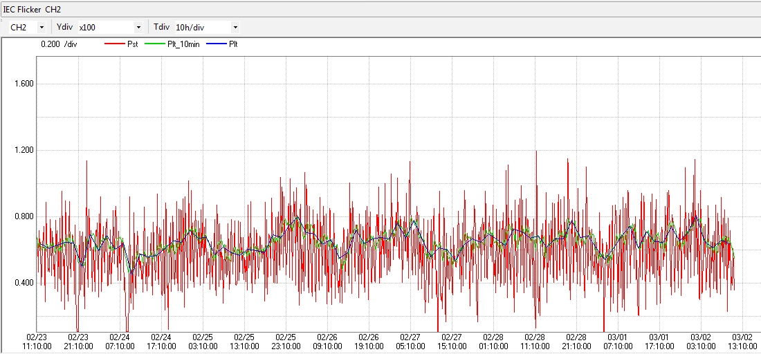
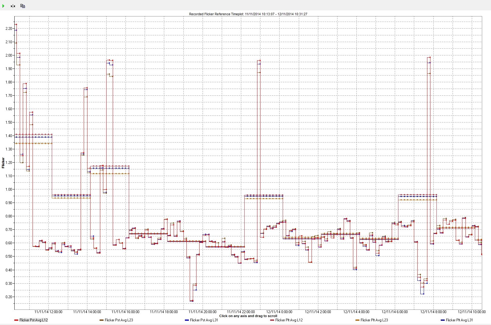
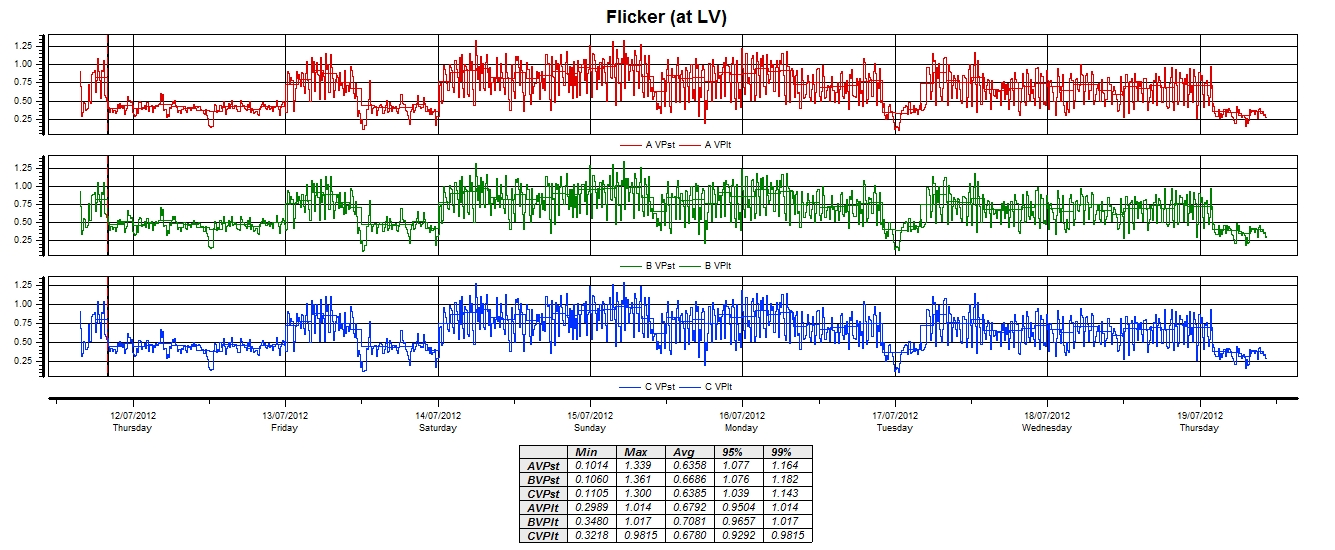
Below are some of flicker trend values in Singapore from my past work. Yes, flicker do exists here.
Flicker recorded at 22kVFlicker recorded in a portFlicker recorded at a Low Voltage Customer
I had the privilege in toying around with the new HDPQ Xplorer earlier today, thanks to Terry Chandler of Power Quality Thailand. Definitely re-affirmed my belief that Dranetz PQ instruments and Dranview (especially) are at least one notch higher against its competitors.
Mr. Harmonics is frequently being blamed when an equipment failed (or when a cable burnt, capacitor bank blown, or a circuit breaker tripped without an obvious fault). Some without due consideration of other simpler factors will blame Mr. Harmonics and his cousins like Mr. Resonance (or perhaps his friend, Mr. Transient – story for another day) straightaway.
Surprisingly, it is a fairly easily accepted reason here. And with power quality instruments getting more affordable these days, it has been becoming quite common to see someone using this new toy, measure current harmonics in percentages of 50-80%, and straightaway concluded that it is indeed a harmonics problem.
Firstly, when it comes to harmonics, we need to know; is it voltage or current harmonics? While there is a common indicator to measure both of them – using the Total Harmonic Distortion (THD) formula (RMS value of the harmonic content expressed as a percentage of the fundamental), one needs to know the pros and cons of using such indicator when applying to voltage/current harmonics.
Usefulness of THD
provide a good indication of how much additional heat will be realised when a distorted voltage is applied across a resistive load
give indication of the extra losses caused by the current flowing thru a conductor
Limitations of THD
unreliable indicator of voltage stress within a capacitor (look out for the peak value instead not THD)
a meaningful indicator for voltage harmonics, as voltage varies only a few % (as referenced to its fundamental)
not so the case for current harmonics as a small current may have high THD but not a significant threat to the system; can be extremely misleading.
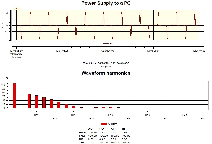
Fig1. sample Iharmonic waveform/spectrum
Here in Fig1, is the current waveform and spectrum of the common switched-mode-power supply to our PC/laptop at work or home. Looking at just its THD% current, one will be extremely alarmed (162%!!). So should all of us purchase harmonic filters for all our homes/offices then? (fact: the actual amperes of this circuit is less than 0.6Amps, and VTHD is only 1.52%)
When it comes to current harmonics, it will be more meaningful to use other alternative indicators such as Total Demand Distortion (TDD), or use absolute amperes (my personal recommendation).
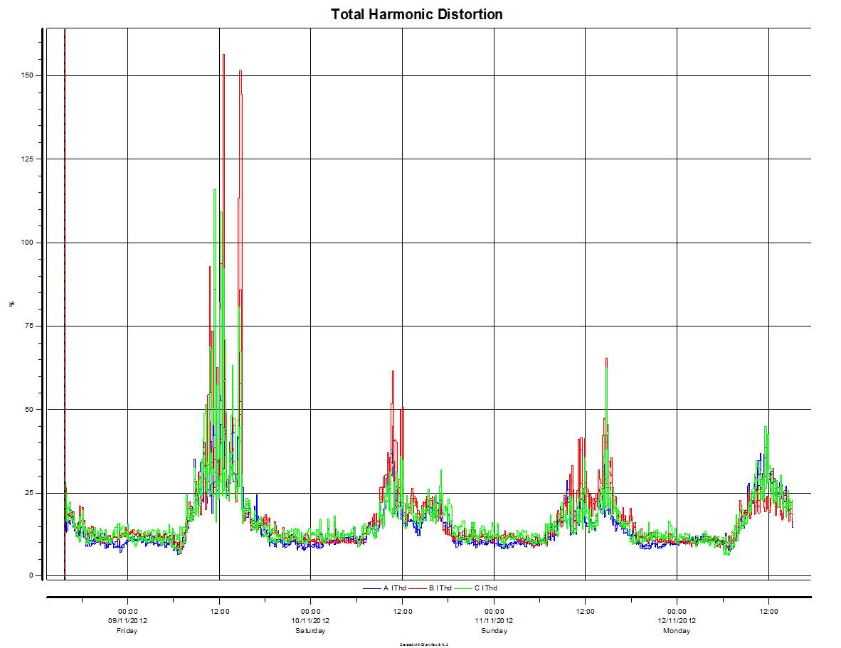
Fig 2 and 3 shows the trending results of current harmonics, presented in THD%, Harmonic Amps and TDD%.
Total Demand Distortion
Current THD is misleading during light load conditions (when I1 is small)
Similar to THD, except that the distortion is expressed as a percentage of some rated load current magnitude rather than as a percentage of the fundamental.
It was reported that the voltage disturbance (lasting about 100ms) yesterday at about 1418hrs was caused by lightning affecting the inter-connector link between Singapore and Johor, Malaysia. Link from the statement by SP PowerGrid.
(FYI: Singapore is inter-connected to Johor at 230kV – a transmission level voltage; any disturbance at this level will typically be ‘seen’ by everyone in Singapore with 1/4 of the island ‘seeing’ the worst dip values).
While there is hardly any blackout moments in Singapore due to how the grid is designed and operated here, voltage dips like the above can actually be quite common. In the last 6 months, there has been 3 of such transmission level-originated voltage disturbances (as taken from our monitoring records; 5/11, 10/9 and 27/7). As electrical faults in the grid (be it caused by cable damage, customer’s installation fault, utility equipment fault or lightning) cannot be totally eliminated (only reduced thru rigorous maintenance, regulations/enforcement etc), customers with sensitive equipment should take measures in protecting their equipment adequately. They should also be aware of this Clause in the Transmission Code (which is also in their Connection Agreement with the Utility).
equipment immunity
This clause basically rules out any ‘compensation claim’ from the Utility due to losses sustained arising from voltage dips. To some, this may seem ‘cruel’, but I believed this clause is fair as the electrical network is interconnected and everyone (Customers, Utility, Gencos) has to play their part. From my experience, the awareness on the need and know-how for protection against voltage dip is still very much work-in-progress here in Singapore. The key to solve voltage-dip related problems is not to seek compensations, but rather to undertake a proper assessment on the vulnerabilities of their equipment against voltage dips and then invest in the right mitigation solutions / methods.
“Explaining the outage, SGX said power is supplied to the data centre from two separate substations, which is then connected to the individual UPS systems. A “momentary fluctuation in power supply from the substations” caused the UPS systems to switch to its internal power source, but these power sources malfunctioned.” – ChannelNewsAsia.