In the early days of my career, I found a great misconception among my colleagues that every power-related problem (for instance relay tripping, equipment failure) requires the use of a power quality (PQ) analyzer to solve it.
Thus, it became an automatic response. The switchboard tripped -> hook up a PQ analyzer. And this occurred for most times without even understanding what the problem was. And for most if not all of these occasions, no real conclusion was formed from the PQ analyzer’s data.
Lesson to Be Learnt:
Hooking up a PQ analyzer without understanding the problem can never lead to any useful results.
Here’s a case (occurred a year ago) where it just required a good engineering sense to solve the problem.
Background
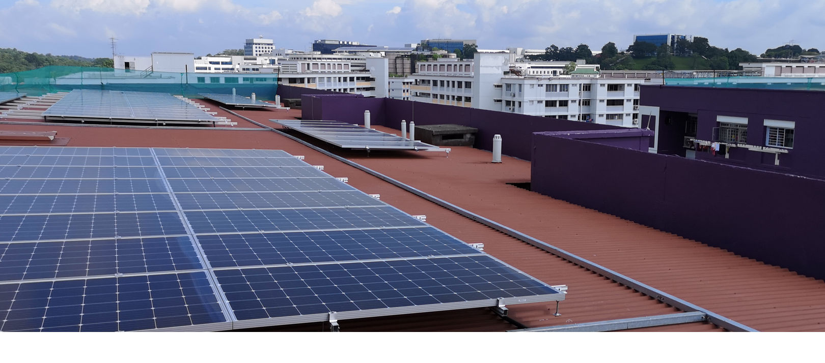
- Old shopping mall in the western part of Singapore.
- Original design of its main switchboard(s) – has one transformer source per MSB only, with no options to couple to another source.
- MSB Incoming Air Circuit Breaker (ACB) – was assumed to be 4P or TPN (three-pole breaker with a switched neutral).
- New ‘coupler-boards’ were installed to allow coupling of loads of two switchboards to one source (eg. Transformer 4 ‘Off’ – all loads on Transformer 4 will be tied onto Transformer 5 – for instance during maintenance or replacement works on Transformer 4)
- Coupler boards’ ACBs were 4P.
The Incident
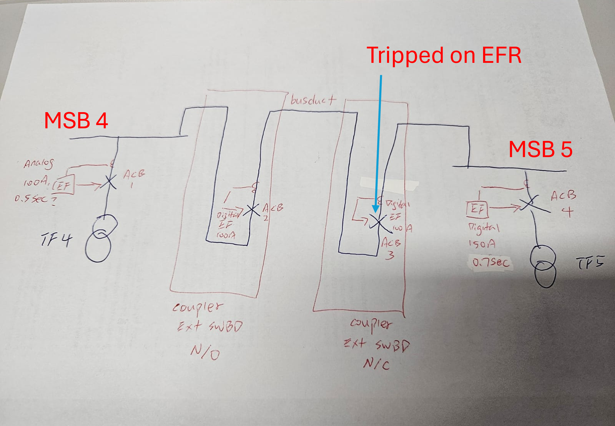
- Transformer 5 – On (ACB 4 = Close).
- Transformer 4 – Off (ACB 1 = Open).
- ACB 2 & 3 = Close.
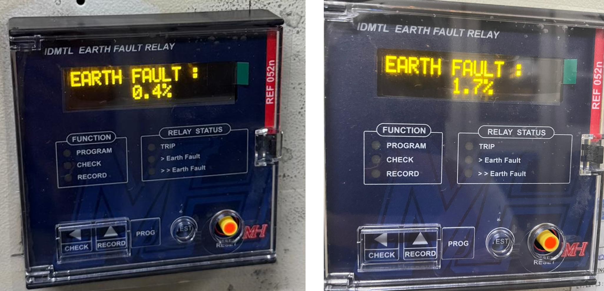
- Earth fault relay at MSB 5 (Transformer 5) was observed to ‘rise’ from 0.2% to 1.2% – 1.8%.
- No trip observed (all switching works were done outside mall’s operational hours).
- Eventually, as the shopping mall started operations and loads picked up – ACB 3 was tripped via the earth fault relay.
- No clear fault was found.
- The two switchboards were decoupled. Transformer 4 was turned on (normalized to default configuration).
- Operations were resumed without further incident.
So, what caused the trip?
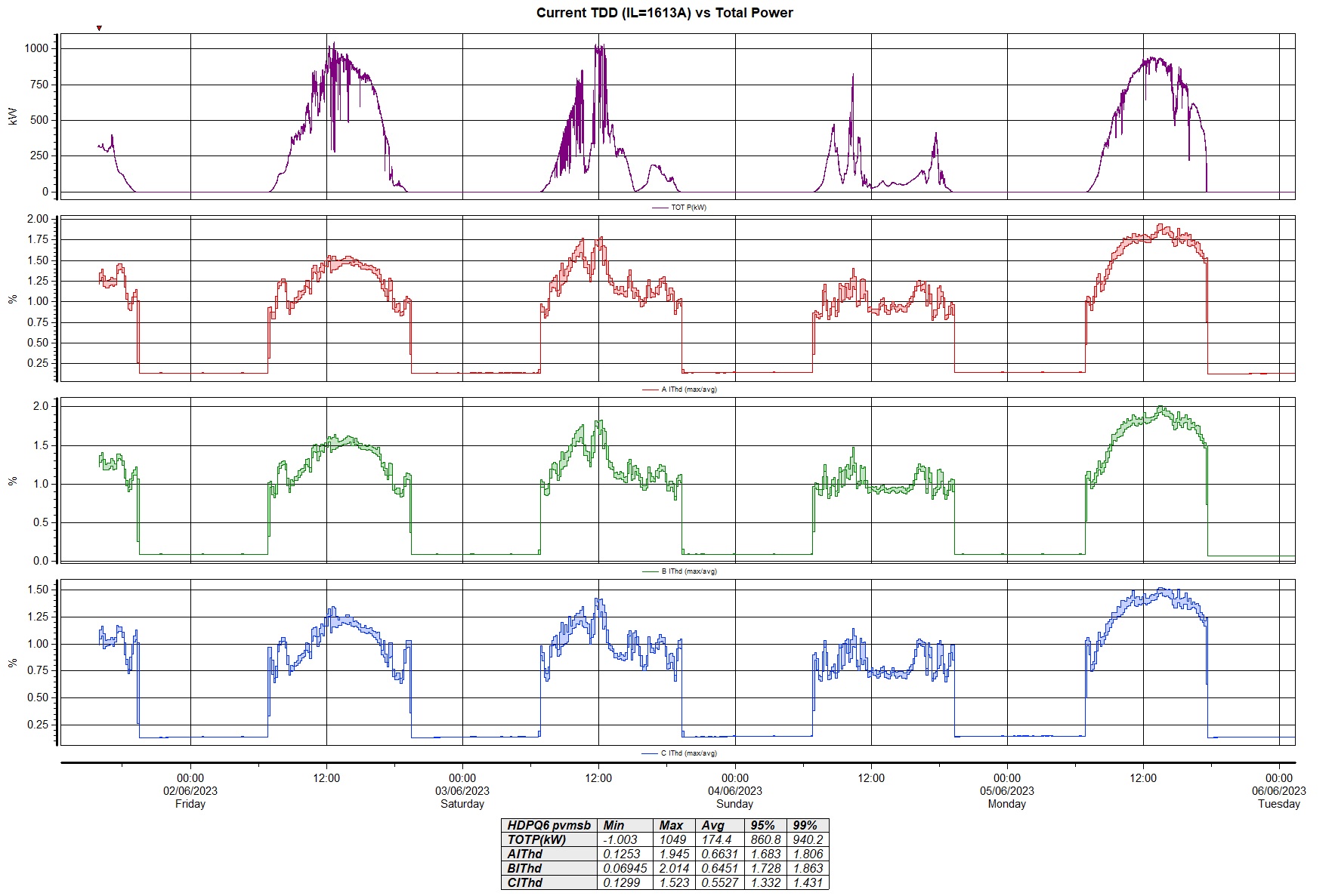
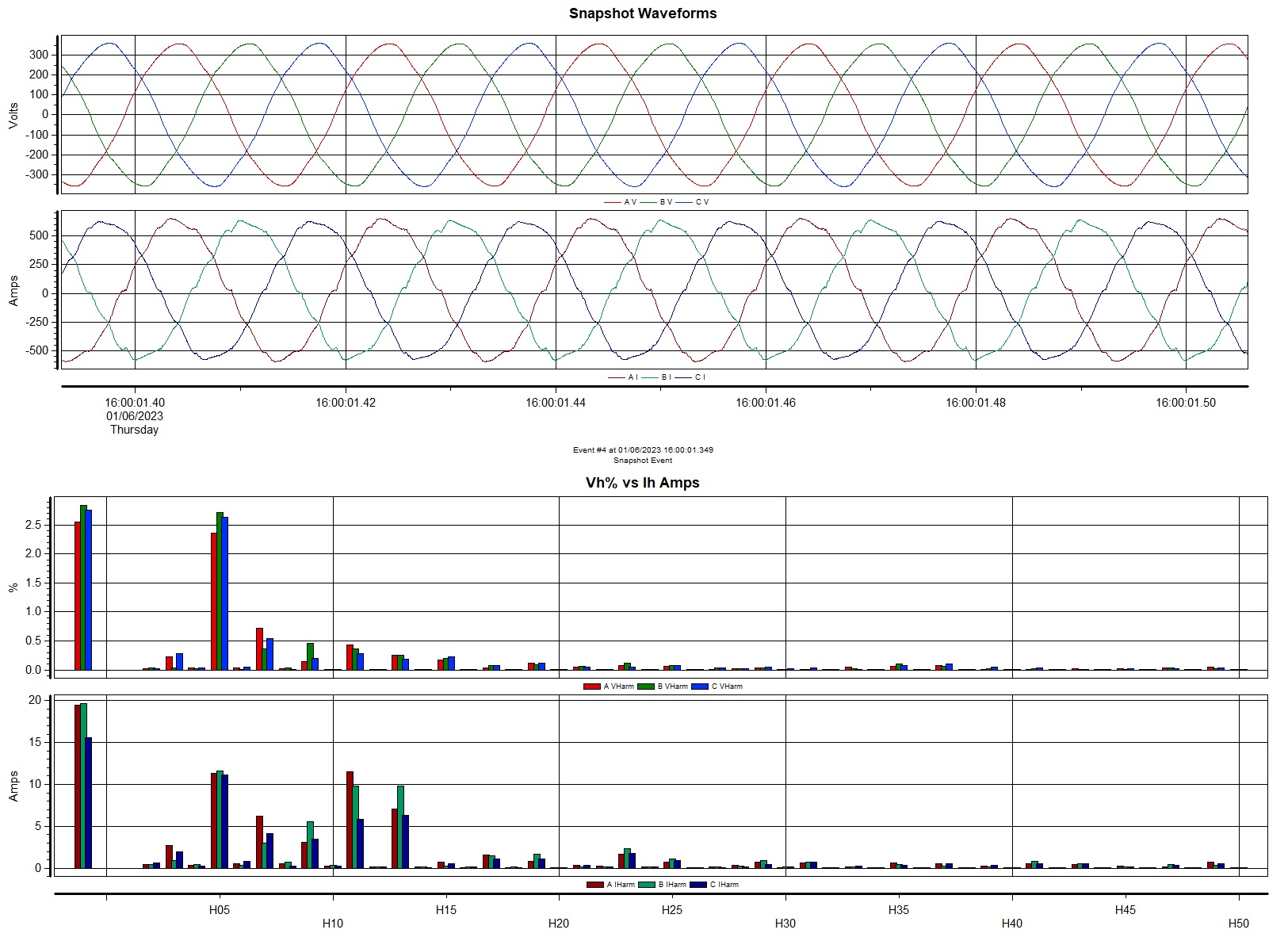
- Shopping mall’s loads are generally single-phase loads. So, current unbalance is to be expected. This will cause some appreciable current in the neutral phase.
- In today’s context, all single-phase loads are electronic loads; high 3rd current harmonic component is to be expected. This further loads up the neutral phase.
- The biggest clue for this incident was that the relay’s ‘earth-fault’ value steadily increased as the mall’s loads picked up.
- My initial suspicion was that the MSB ACB isn’t 4P or TPN – rather, it was a three-pole ACB with a neutral link (meaning its neutral isn’t isolated when the ACB is OFF).
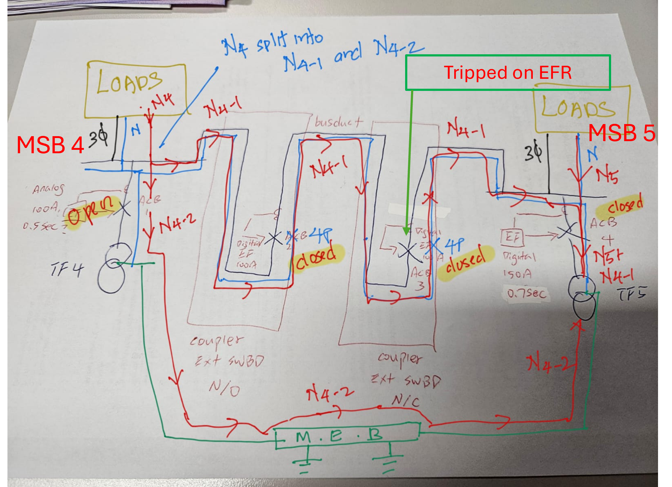
- This caused the neutral current from the loads at MSB 4 to split up (N4 = N4-1 + N4-2).
- Thus, the earth fault relay will ‘not see’ the return of the ‘full’ neutral current.
- Eventually, when the neutral current was high enough, it triggered the earth fault relay at ACB 3.
- On-site checks confirmed my suspicion.
- Thus, for this coupling (MSB 4 loads to be supplied by MSB 5) to work seamlessly, the neutral link at ACB 1 has to be removed, before being coupled.
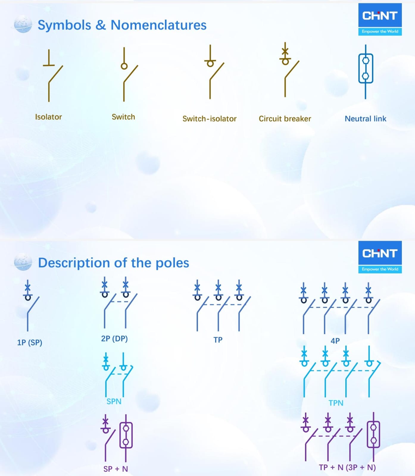
- Additionally, in the local scene, “TPN” vs “TP+N” gets frequently mixed up (unfortunately).
- Below is a diagram from one of CHINT’s presentations to illustrate the different poles of a circuit breaker.