Earlier, our office recorded a ‘shallow’ dip at approximately 1919hrs. Tell-tale signs from other neighbouring monitoring sites show this could be a transmission-level fault. Shall await for the report from the utility tomorrow.
Update 15/9/2014 from the Utility: Customer installation fault at Jurong Island
Noting how this dip due to a ‘customer installation fault’ can be seen in many areas, those ‘in the know’ will know who is the Customer here.
Just awhile ago, if you are one of the facilities’ guys, you probably had to scramble around because of dip alarms, standby generator cutting in or chiller drop-off.
Another 230kV fault was registered; affecting the South side of Singapore the most, suggesting a 230kV fault in the South block.
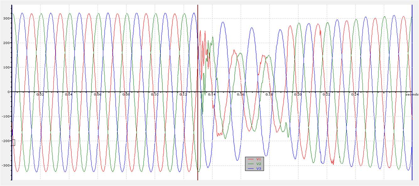
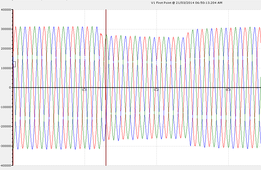
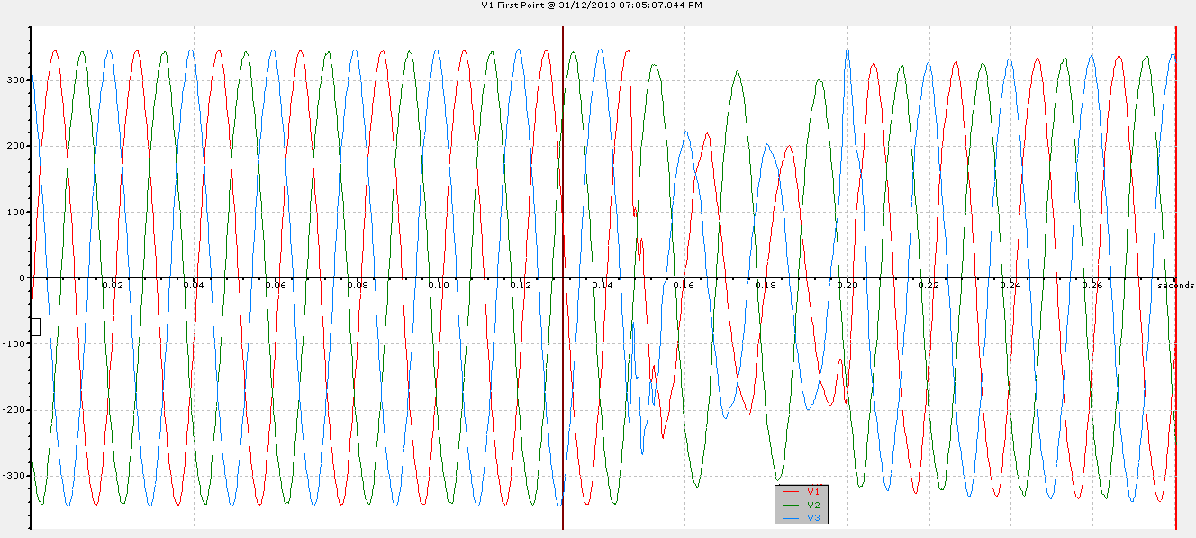
Here is a voltage waveform from one of our sites in the South.
Voltage waveform is taken at Low Voltage (L-N). It will mirror what is seen at 22kV and above (L-L).
(i.e L1 phase at LV is equivalent to L1L2 at 22kV).
The waveform here shows that there was a single phase fault (L2) at 230kV.
Here it was registered; worst case dip of more than 50%. Other blocks in Singapore (North, West, East) would also have seen this fault, albeit at less severe values.
On a happier note, Selamat Hari Raya Aidilfitri (in advance) to my fellow Muslims. Maaf Zahir Batin.
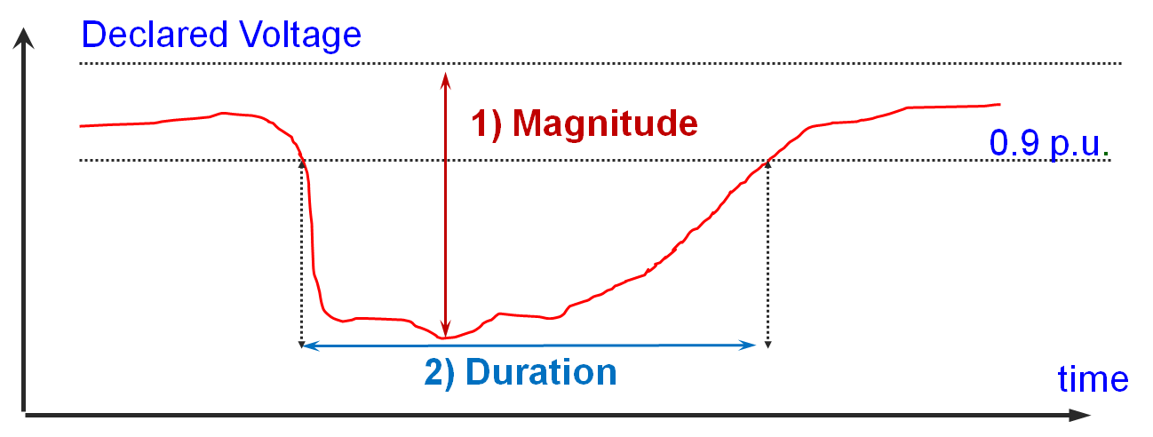
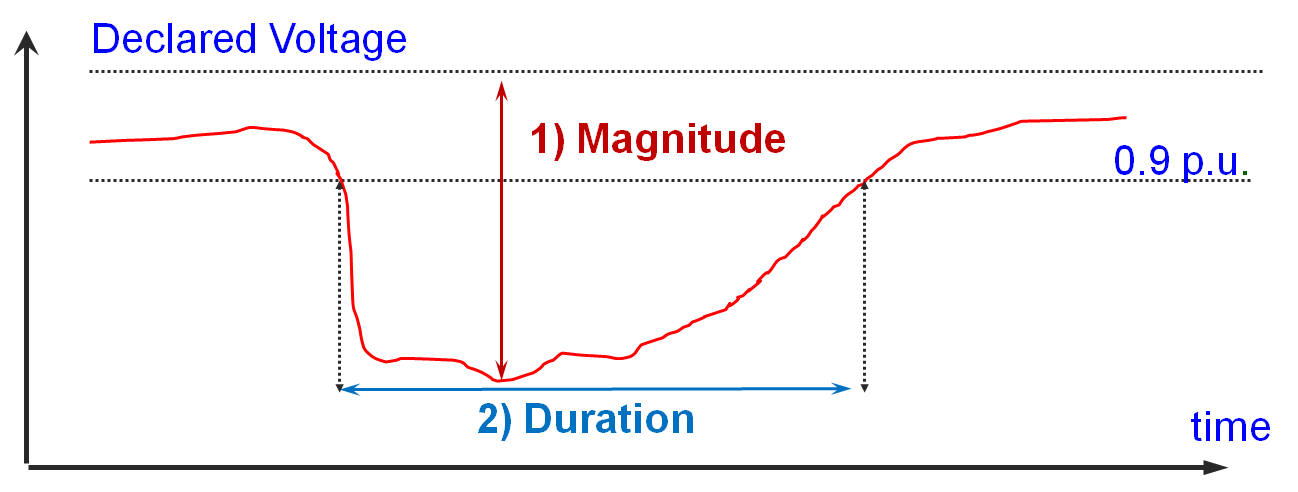
In Singapore, a voltage dip is defined as per EN50160; “a sudden reduction of the supply voltage to a value between 90% and 1% of the declared voltage, followed by a voltage recovery after a short period of time; between 10ms and up to a minute”. Typically it lasts less than 200ms. Two things matter in the definition of a dip. See Figure 1.
1) Magnitude: This typically reflects the fault severity and also the proximity of the monitoring point to the fault location.
2) Duration: The timer starts when the voltage falls below the 90% threshold and ends when all voltages are equal to or above the 90% threshold. This is very much dependent on the time taken to isolate the fault and the nature of loads connected.
Fig1: Definition of a Voltage Dip
The Utility company here has a power quality monitoring system in place; from voltages 22kV and up to 400kV. As these are 3 phase 3 wire systems; line to line voltages are used in the definition of a dip. When there is such a dip, the worst dip by magnitude and its duration will be published by the Utility.
There is a significance of such definition being used in the 66kV and 22kV networks, whereby it is a resistively earthed grounded system (thru the neutral ground resistor). Here, a single phase fault will not be a registered as a voltage dip as the other two non-faulted phases will swell; ‘compensating’ the faulted phase. This will result in a drop of voltage (line to line) of usually less than 10% (hence not a dip). The Utility company here described such events as ‘Voltage variation’.
In recent times, voltage dips seem to be quite frequent in our office at 16 Boon Lay Way, Tradehub21. Tradehub21 is one of the many commercial buildings located in this Jurong East region; near to the International Business Park and also shopping malls like IMM, JCube, JEM and Westgate.
In the last 5 months, our office has recorded a total of 3 voltage dips; two originated from the Utility’s 230kV transmission fault and one which occurred last Friday due to a 22kV Customer’s Installation fault (along Jurong Gateway Road). It is fortunate in a way that this area is not a Semiconductor Hub, as just one dip will have costly implications on a semiconductor plant, let alone three.
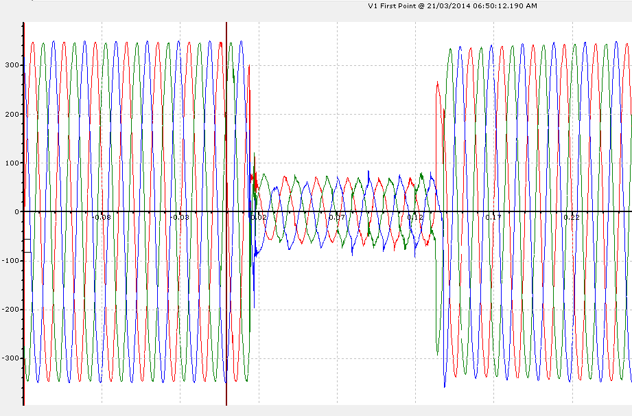
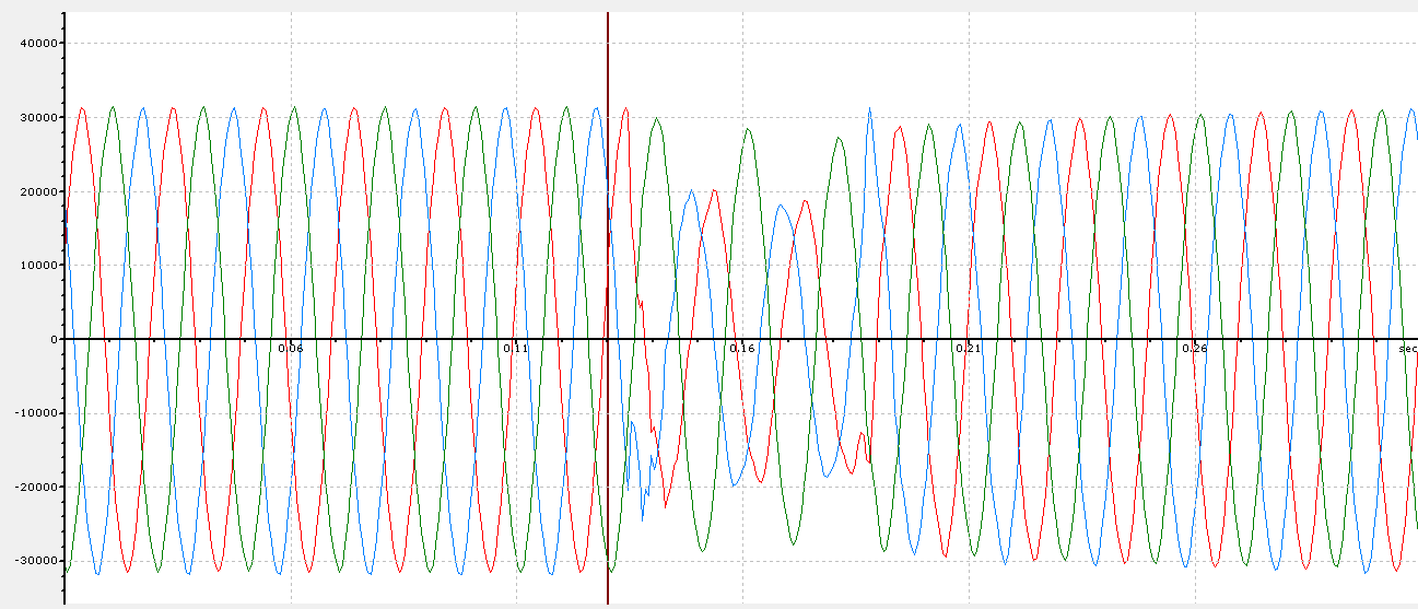
Fig2: Voltage dip (dip by 80%) 21-03-2014 0650hrs (QPM Office – seen at 230V). A three-phase 22kV fault; Dip magnitudes at 22kV will be similar.Fig3: Voltage dip (dip by 43%) 31-12-2013 1905hrs (QPM Office – seen at 230V). A single phase 230kV fault; 22kV dip waveforms and magnitudes will be largely similar due to the proportionality between a 22kV line to line voltage and a 230V line to neutral voltages (Dyn11).Fig4: Same voltage dip event as Figure 3 but seen at 22kV at a QPM-managed site near Gul area. 230kV Singapore Grid is solidly earthed; hence during a single phase fault, the other two non-faulted phases will also drop slightly. Here was an L1 (red phase fault); affecting L1L2 and L3L1 significantly. Hence you can notice both L1L2 and L3L1 ‘dropped’.Fig5: Voltage dip (dip by 48%) 30-10-2013 1413hrs (QPM Office – seen at 230V). A single phase 230kV fault.
However, this is not to say that commercial buildings and shopping malls are immune to the effects of voltage dips. Here are the common known effects of voltage dips in a commercial building / shopping mall setting.
1) Chiller System
It is a known fact that chillers plants and its related equipment are sensitive to voltage dips. Relays, control contactors and the electronic/computerized controls may drop off during dips, hence causing the trip. The impact to building occupiers is small; as these effects are likely to be transparent to them; or at most minor discomfort due to a slightly raised ambient temperature.
Possible Mitigation
The sensitivity is sometimes made intentionally (and at times over-conservative) as there is a concern on possibilities of damage to the motor due to the high transient current upon normalization of system voltage (hence it is better to trip). A consultation with the Chillers’ OEM is almost necessary if one decides to protect its control circuits. This is to ensure that it will not result in damaging the motor.
Chiller controls can be secured with on-line UPS or voltage dip mitigation solutions like MiniDySC from SoftSwitching Technologies. Sensitive relays can be identified and replaced. Another option is to enable the Chiller for ‘Auto-Restart’ function if allowable.
Having an internal thorough proper restarting procedure of chillers in the event of tripping due to voltage dips in the network is also a form of ‘mitigation’ as it reduces the downtime of the Chillers. This usually needs close co-operation with the Utility company or install a permanent power quality monitoring system in the building to determine where the origin of the voltage dip (internal fault or fault from the Grid).
2) Lighting Circuits
During a voltage dip, flickering of the lights can be observed. In general, problems only arise when High Intensity Discharge (HID) lamps are used. These types of lightings are known to be sensitive to voltage dips and temporarily extinguish after a voltage dip. Re-ignition time usually takes up to 10 minutes.
Possible Mitigation
For HID lamps applications, one possible mitigation is to re-fit with “hot re-strike” igniter for instant lighting restoration. In the use of HID lamps in “critical areas”, it is best to deploy them alongside normal type of lightings (for eg. Fluorescent lightings), so as to avoid a ‘total blackout’.
In addition, occurrence of voltage dip across three phases is rare; hence the even distribution of lightings across the 3 phases can avoid a ‘total blackout’ during a voltage dip.
3) Escalators
During a voltage dip, the control contactors and PLC of the escalator may drop off. Another cause could be the activation of the phase monitoring relay, which is meant to activate upon loss of mains.
Governed by the Singapore Standard CP15:2004, escalators are designed to be brought to rest in a largely uniform deceleration in the event of loss of mains (thus not a safety concern). However public image may be affected.
Possible Mitigation
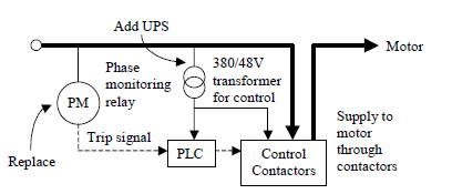
The control contactors and PLC can be secured through adding an uninterruptible power supply (UPS) and the phase monitoring relay can be upgraded to a relay equipped with a time delay for up to 0.2 sec. See Figure 6. This is based on CLP Power Hong Kong’s experience in voltage dip mitigation for escalators. It is also documented in Hong Kong’s” Code of Practice on the Design and Construction of Lift & Escalator.”
Fig6: Simplified SLD of Escalator Control – Recent Development in Power Quality by Dr F.C Chan (CLP Engineering Limited)
My personal accounts in conducting voltage dip tests on some of these escalators showed that in general, a voltage dip of more than 40%, regardless of duration that affects the supply to the control circuits will result in the escalator to stop. Mitigation equipment such as the MiniDySC was found to be an effective solution against such events.
A full implementation of such mitigation however will need further tests with the OEM escalator’s specialists to ensure that safety features related to its braking will not be compromised. Additionally, it may also require slight deviations from the existing CP15 as similarly re-defined in Hong Kong’s Code of Practice for Lifts & Escalators.
4) General Circuits
General circuits served by miniature circuit breakers (MCB) have also been reported to have tripped after a voltage dip. Immediately after a voltage dip, some MCBs may tripped due to large in-rush current drawn by motors, switch mode power supply, circuits containing control transformer, etc.
Possible Mitigation
Normally, if the MCBs are properly sized to cater for such ‘inrush’, the circuits should not trip.
SEMI F47
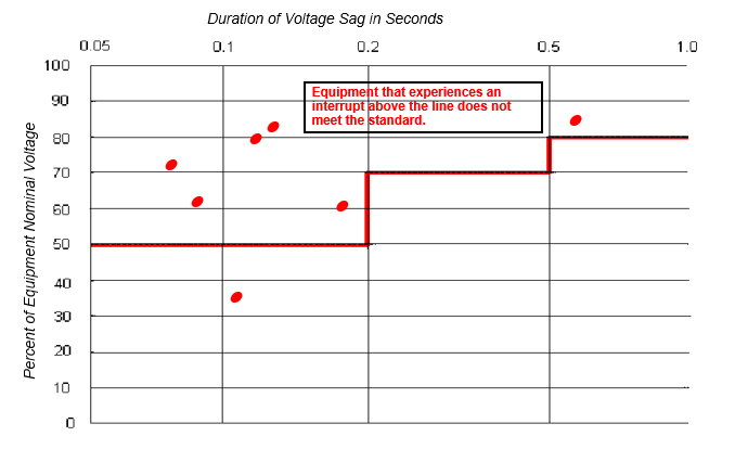
When it comes to voltage dip mitigation, the word “SEMI F47” will most likely to crop up. Without going into details, it is basically a minimum ride-through specification for semiconductor tools and processes as the semiconductor industry are most prone to voltage dips due to the nature of its operations. See Figure7.
However it must be noted that even such specification does not translate to 100% availability during a voltage dip as dips that are required for compliance with this specification occur between one phase and neutral, or between one pair of phase, at a time only. Hence for these 3 voltage dip incidents mentioned, a SEMI F47-rated equipment will also not guarantee you 100% availability.
Fig7: SEMI F47 0706 – Specification for Semiconductor Processing Equipment Voltage Sag Immunity
To put in simply, in the SEMI F47 specification, an economical balance has been chosen such that semiconductor processing equipment which meets the requirements will be immune to most, but not all, real-world voltage dips at semiconductor plants.
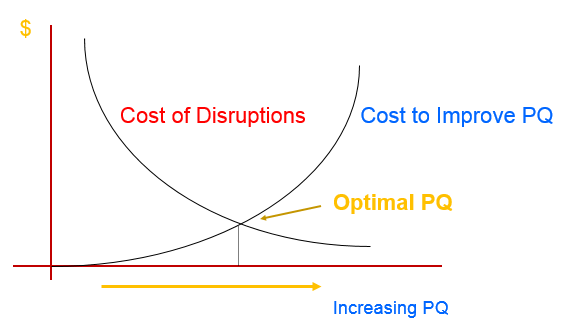
Similarly if one is to consider mitigation equipment, a cost-benefit analysis has to be conducted as such mitigation do not come cheap. A historical dip statistics of the area from the Utility Company should always be among the first things to be obtained.
Fig8: Cost-Benefit Analysis
Faults (and hence voltage dips) are inherent in all power systems in the world. The frequencies of such occurrences can be minimized but not eliminated. Minimization requires the cooperation of all Stakeholders; the Regulator, the Utility company, the Licensed Electrical Engineers and Customers alike through regulations, regular preventive maintenance and condition monitoring.
And if need be, voltage dip mitigation equipment can be employed for those with sensitive operations or processes, albeit it will come at a price. But the price of leaving it to chance may even be greater (see Figure 8). Ultimately the user has to decide.
Earlier in the morning, our office (in Jurong East) captured a voltage dip of about 80%. See Figure 1 (3 phase fault – seen at Low Voltage)
Figure 1: Dip Office 21-03-2014 0650hrs
Another monitoring site in Gul area also monitored a variation as seen in Figure 2. It was likely to be a distribution level (22kV) fault. Update: Official source said it was due to a Customer Installation fault at Jurong Gateway Road
In Singapore, low tension voltages supplied by the utility has to meet the voltage regulation limits of +/-6% of 230V (single phase) / 400V (three phase). While this is usually the case, there will be times when voltages can be excessively high during low loading periods primarily in areas whereby there are a large proportion of commercial or industrial blocks.
While equipment’s ability to handle steady state voltage variation varies from one equipment to another, in general any equipment which is constantly ‘exposed’ to long periods of overvoltages will suffer from a reduced lifespan. IEC TR 61000-2-14 showed a reduced lifespan of almost 50% when a filament lamp was operated at 5% higher than its rated voltage. Though it will not be as severe for other types of lightings, one should still expect shorter lamp/ballast life.
And with ‘energy savings’ being the buzz words these days, one may consider to reduce the voltages as ‘seen’ by the equipment even further. This is where voltage optimisation comes in. The interest on how reducing voltages can be used to save electric energy has been around for many years now. The results however have been mixed as its effectiveness is very much dependent on the type of loads and its applications.
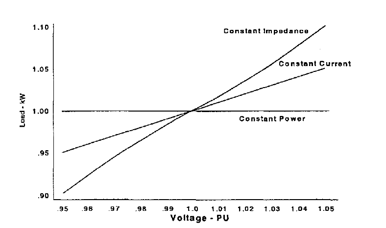
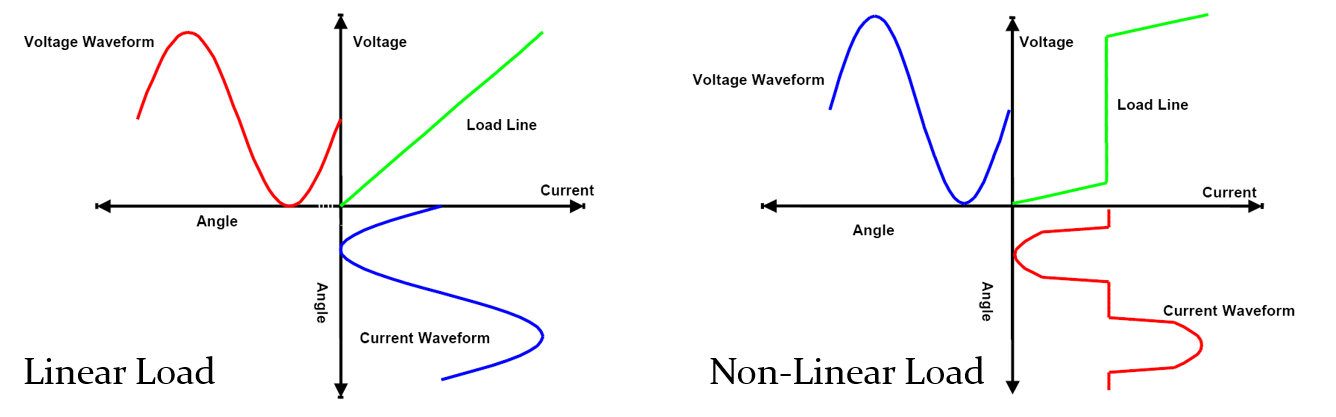
In general, loads can be categorized into 3 Types; i) Constant impedance: Power is proportional to (Voltage)2 .
ii) Constant power: Demand is constant regardless of Voltage.
iii) Constant current: Demand is proportional to Voltage.
Its relationship to voltage & loading is shown in Figure 1.
Figure 1: Actual demand created by “1 kW” of each of the 3 Types of Loads, as a function of voltage supplied to them – Source: Power Distribution Planning Reference Book (H.Lee Willis)
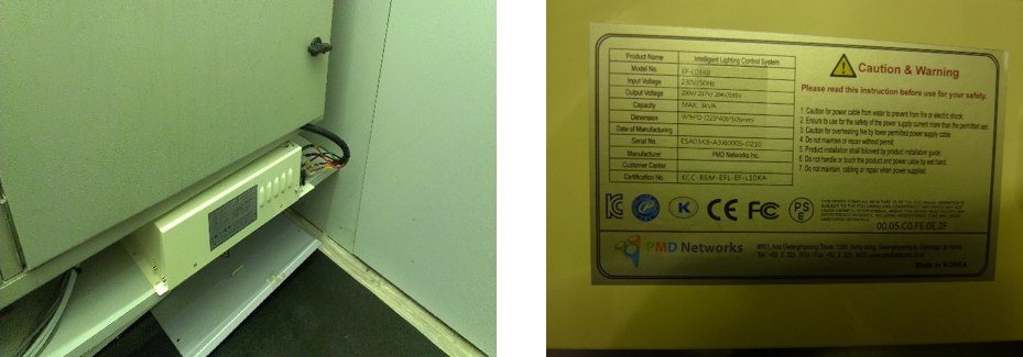
Trial Setup
An area in our office was recently equipped with such energy savings device, for the lightings. In our trial, it basically functioned like a “step-down” transformer, reducing the voltage to the lighting circuits. The device has 3 voltage reduction levels; each is a ~13V step down from the incoming voltage.
Figure 2: Energy Savings Device
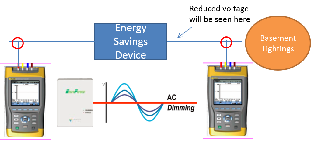
Two sets of Fluke 435 Power Quality Analyzers were also installed, monitoring the input and output of the energy savings device; when it was operating at 3 different voltage step levels. Its aggregation interval was set at 1 second and measurement was recorded for 1 hour for each voltage step level.
Figure 3a: Trial Setup
Figure 3b: Area Under Test
Lux readings were also taken at various spots in the area, for comparisons against the following guidelines to ensure resultant lux values did not go lower than the recommended levels.
Table 1: Selected Lux Levels Guidelines
Guidelines
Recommended Lux Levels
AS/NZS 1680.2.2 – Recommended Lux level for general office tasks
320 lux
HK Occupational Safety & Health – A guide to work with computers – Recommended illumination for computer desk work
300-500 lux
SS CP87 2001: Industrial Illumination – Recommended Lux level for routine office work
320 lux
Results
Table 2: Measurement Results (selected)
Parameters
* measured at input
Without energy savings device
Step 3
(reduction of approx 39V)
Voltage
238.94V – 242.02V
238.49V – 240.44V
Current
8.778A – 9.03A
5.197A – 5.272A
Power
1207.437W – 1249.052W
811.404W – 825.791W
Power Factor
0.57 – 0.58
0.65
Energy Consumed
1.239 kWh
0.818 kWh
Interestingly, most occupants (with the exception of one person) working in this affected area did not notice the dimming of the lights.
In this short trial, the reduction of the voltage to ‘Step 3’ (which resulted in the dimming of the lightings – lux value reduced by 53 lux on average) achieved a 34% of savings in kWh consumption.
Conclusion
Voltage reduction does bring savings in energy, if applied on the right load and application.
Before one decides to use such devices, it is important to check what type of loads will be connected. As seen in Figure 1 earlier, not all loads will benefit in terms of energy savings when voltage is reduced. Even in cases of lightings, not all types will be suitable.
Its application matters as well. There is little benefit if resultant lux level becomes too low and the employee has to use a desk lamp to complement the office lightings. Or that an equipment has to operate longer to achieve the same objective (eg. A kettle to run longer to boil the same amount of water, under a reduced voltage state).
Another transmission level (230kV) fault happened earlier at 19:05 hrs.
Places in the Western area would have seen the worst dip magnitudes /duration ( ~ 50% dip by)
* Will update with a waveform from one of our PQ monitors in the West soon.
Till then; Happy 2014 ! (in advance)
Update: 2/1/2014
From the following waveforms, we can conclude that there was a 230kV single phase fault on Phase L1 (red)
Voltage Dip Waveform Captured In the West (22kV) – Dip by 40.83%, 78ms
Voltage Dip Waveform 31-12-2013 1905hrs (at 22kV)
Voltage Dip Waveform Captured In the West (Low Voltage-230V) – Dip by 43%, 80ms
Voltage Dip Waveform 31-12-2013 1905hrs (at Low Voltage)
Notes:
A transmission level fault will cause an islandwide voltage dip.
Here, in Singapore. a voltage dip is defined as a drop of more than 10% of the nominal voltage (Line voltage). It typically lasts around 200ms.
In Singapore, the transmission network consists of a 400kV network, overlayed onto 4 x 230kV blocks. The 230kV blocks were split up in the mid 2000s, for controlling of fault level.
It has inherently brought an advantage: Minimize the impact of a voltage dip due to a 230kV transmission fault to just that particular block.
Hence in a 230kV fault, only connected customers in that particular block which the fault occurred will ‘see’ severe dip values (usually in the ranges of 40-50% dip by magnitude for single phase 230kV faults); Customers in the lower voltage levels (66kV, 22kV…) of that block will see similar (as seen at 230kV) dip severity or less (slightly).
The other 3 blocks will see significantly less severe voltage dip or just a slight variation of the nominal voltage.
Definition: Temporary reduction of the r.m.s voltage at a point in the electrical system below 90% threshold of the declared nominal voltage, between 10ms and up to a minute.
Voltage Dip (RMS Trend)
Simply speaking, a sudden voltage drop of more than 10% of the declared nominal voltage. The utility in Singapore has in place a Power Quality Monitoring System (PQMS) from 22kV voltage level upwards (all the way to 400kV). These are three-wire three phase systems; and hence line to line voltages are used in defining a dip.
There is a significance of such definition being used in the 66kV and 22kV networks, whereby it is a resistively earthed grounded system (thru the neutral ground resistor). Here, a single phase fault will not be a registered as a voltage dip as the other two non-faulted phases will swell; ‘compensating’ the faulted phase. This will result in a drop of voltage (line to line) of usually less than 10% (hence not a dip). The utility here described such events as ‘Voltage variation’.
Two things matter when it comes to describing a voltage dip.
1) Magnitude of the dip
This typically reflects the fault severity and also the proximity of the monitoring point to the fault location.
2) Duration The timer starts when the voltage falls below the 90% threshold and ends when all voltages are equal to or above the 90% threshold. This is very much dependent on the time taken to isolate the fault and the nature of loads connected.
Normally a voltage dip here in Singapore will lasts less than 200ms (10 cycles). This is about the average time the primary protection takes to isolate the fault from the network.
Usually a longer duration will suggest a somewhat sluggish protection relay operation.
Typical causes of a voltage dip in Singapore:
1) Equipment / cable faults in the utility network.
2) Equipment / transmission line faults in Tenaga Nasional Berhad (TNB) network (Singapore is connected to Malaysia at 230kV).
3) Customer Installation faults.
4) Cable damage by earthworks.
5) And to a very small extent, load switching like motor starting.
Singapore’s electricity regulator, the Energy Market Authority (EMA) publishes cases of voltage dips on its website.
Earlier today, at about 2 plus in the afternoon, you might have noticed your office lights flickered, the escalators came to a standstill or that the chillers had tripped.
Enough clues to guess what could have been the cause?
Yes, you guessed it right. There was a transmission level fault, hence causing an islandwide voltage dip.
Here, in Singapore. a voltage dip is defined as a drop of more than 10% of the nominal voltage (Line voltage). It typically lasts around 200ms.
In Singapore, the transmission network consists of a 400kV network, overlayed onto 4 x 230kV blocks. The 230kV blocks were split up in the mid 2000s, for controlling of fault level.
It has inherently brought an advantage: Minimize the impact of a voltage dip due to a 230kV transmission fault to just that particular block.
Hence in a 230kV fault, only connected customers in that particular block which the fault occurred will ‘see’ severe dip values (in the ranges of 40-50% dip by magnitude); Customers in the lower voltage levels (66kV, 22kV etc) of that block will see similar (as seen at 230kV) dip severity or less (slightly). The other 3 blocks will see significantly less severe voltage dip or just a slight variation of the nominal voltage.
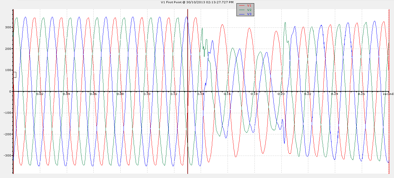
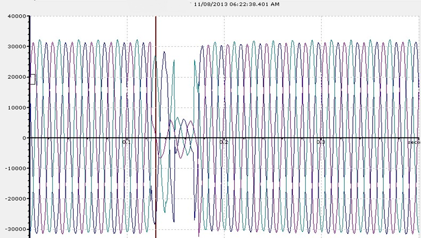
This is what happened earlier. Below is the 22kV (Line to Line) voltage dip snapshot, captured from one of the monitoring sites in the western part of Singapore.
22kV Voltage Dip Waveform 30-10-2013 1413hrs
Monitoring sites in other parts of Singapore also registered similar dip patterns, suggesting a transmission level fault.
This brings me to the conclusion that
1) This was a 230kV single phase fault on the L3 (Blue phase) in the western part of Singapore. UPDATE 31/10: Official Letter from SP PowerAssets: 230kV Cable damage – between Tuas Substation and Jurong Pier Substation at about 2:13 PM, 30/10/2013.
2) An L3 fault occurred. This affected V23 and V31 significantly. Hence you can notice both V23 and V31 ‘dropped’.
Singapore’s 230kv network is solidly grounded; hence any single phase fault will cause the other two non-faulted phases to ‘drop’ slightly too. This is unlike in a resistive earthed grounded system, (thru the Neutral Ground resistor) where the other two non-faulted phases will swell.
Here it also shows the advantages of having a power quality monitoring system installed. With both voltage and current waveforms recorded during a dip, it will assist the experienced engineer in analyzing whether the drop in voltage was caused by a fault downstream (internal fault) or originated from the grid (external fault); and hence assist him in quicken the restoration time for equipment that could have tripped due to the voltage dip.